
KGPS-1 Constant power main control board
- Oct 17, 2019
- 2 min read

KGPS-1 constant power thyristor intermediate frequency power supply control board is mainly composed of power supply, regulator, phase shift control circuit, protection circuit, starting calculation circuit, inverter frequency tracking, inverter pulse formation, pulse amplification and pulse transformer. In addition to the regulator, the circuit is digitalized, and the rectifier trigger part does not need any adjustment. It has the characteristics of high reliability, high pulse symmetry, strong anti-interference ability, fast response, etc., and due to the phase sequence adaptive circuit. There is no need for a synchronous transformer. Therefore, the phase adjustment sequence and the synchronization work are eliminated in the field debugging. Only the gate line of the KP thyristor needs to be connected to the corresponding terminal of the control board, and the rectification part can be put into operation.
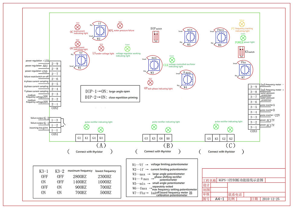
Control circuit characteristics and principles KGPS-1 constant power IF voltage control board is the fourth generation control circuit developed by our factory. It has the following characteristics: ● The control board is suitable for parallel inverter. Used for voltage control of various metal smelting, insulation and induction heating equipment. ● The control board is a fully integrated control board with digital triggering. It has high reliability, high precision, easy debugging and few relay components. ● Advanced sweep start mode allows the operator to achieve 100% successful start without having to select the start voltage and start frequency. ● Automatically follow load changes, with non-faulty automatic restart function and automatic power adjustment function during operation. ● It has ideal interception, interception, precise off time and inverter control angle to ensure reliable operation of equipment. ● Suitable for controlling 100KW~2000KW/400~8000HZ intermediate frequency power supply. The entire control circuit is made into a printed circuit board structure in addition to the inverter final stage trigger circuit board. Functionally, it is divided into a rectification trigger part, a regulator part, and a start-up calculation part.


Comments